Cylinder heads. What
kind are there ? which fits? Porting? What
to do and what to buy, and what are the specs?
T.O.C
1. Cylinder head
2. Springs
3. Tappets
4. Valves
5. Valve guides
6. Intake
7. Porting 1 on 1
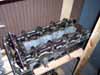
Cylinder head
The cylinder head is precision casted in a metal alloy.
Specs (source SAAB 900 workshop manual,
0 technical data):
| Height,
new head |
140.5
mm +/- 0.1 |
5.533
in +/- 0.003 |
| Height,
min after regrind |
140.1
mm +/- 0.1 |
5.516
in +/- 0.004 |
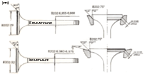
There are different heads B202, B212, B234 (longhead), B204 (shorthead), B234 (shorthead)
B202 asymmetric ports
SAAB Part no: 752170
Intake port (height, width): 28 mm,38 mm
Exhaust port (height, width):
27mm,42 mm
Combustion space volume: - cc
Flow intake: - CFM
Flow exhaust: 160* CFM

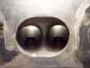
B202 OG asymmetrical intake
B202 OG asymmetrical
B202 OG asymmetrical
B202 OG asymmetrical
combustionspace
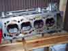
B202 symmetric ports (old generation, with oil feed pipes)
SAAB Part no:--------
Intake port (height, width): 28 mm,38 mm
Exhaust port (height, width): 27mm,42 mm
Combustion space volume: - cc
Flow intake: 153* CFM
Flow exhaust: 160* CFM
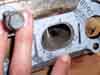
<picture of head>
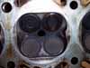
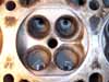
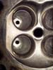
B202 symmetric ports (new generation, no oil feed pipes)
SAAB Part no: 9107376
Intake port (height, width):
-- mm,-- mm
Exhaust port (height, width):
-- mm,-- mm
Combustion space volume: - cc
Flow intake: 182* CFM
Flow exhaust: 165* CFM
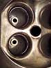
<picture of head>
<picture of intake port>
<picture of Exhaust port>
<picture of combustion space>
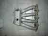
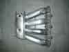
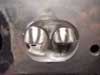
B212 & B234 "longhead"
SAAB Part no: 911535
Intake port (height, width):
31 mm,43 mm
Exhaust port (height, width): 27mm,42 mm
Combustion space volume: - cc
Flow intake: 192* CFM
Flow exhaust: 170* CFM
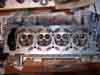
B212 head
B212
intake
B212
combustionspace
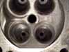
B204/B234 (T5) "shorthead"
SAAB Part no: --------
Intake port (height, width):
-- mm,-- mm
Exhaust port (height, width):
-- mm,-- mm
Combustion space volume: - cc
Flow intake: 228* CFM
Flow exhaust: 17x* CFM
<picture of head>
<picture of intake port>
<picture of Exhaust port>
<picture of combustion space>
*data from Group9
Springs
The springs.
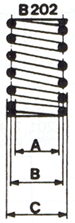
| A |
Min
19.6
mm |
0.7717
in |
| B |
24
mm |
0.9449
in |
| C |
Max 28.4
mm |
1.1181
in |
Specs (source SAAB 900 workshop manual, 0 technical data):
| Length,
mounted |
37.0
mm |
1.46
in |
| Length,
free |
45.1
mm +/- 1.5 |
1.77
in +/- 0.05 |
Length,
loaded to
595-645 N (131-141 lbf) |
28.4
mm |
1.12
in |
The stock springs are
good for up to aprox 7000 RPM.
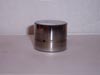
Tappets
The tappets are hydraulic and does not need any adjustment.
Tappet
Specs (source SAAB 900 workshop manual, 0 technical data):
| Diameter |
32,959-32,975
mm |
1.2976-1.2982
in |
| Height |
26
mm |
1.02
in |
| Bore
in head |
33,000-33,016
mm |
1.2992-1.2998
in |
The stock tappets might
start to "float" at aprox 7200 RPM.
Valves
The valves
are precision made and is not needed to be replaced unless they are worn or
damaged.
| Intake
valve size |
32.0
mm |
1.26
in |
| Exhaust
valve size |
29.0
mm |
1.14
in |
OBSERVE! the valves are stellite covered, and shall not be
machined! In some porting recommendations a back-cut is done on top of the valve
to increase flow. This
is not recommended on stock SAAB valves.
Valve guides
The guides are made in really durable steel.
Specs (source SAAB 900 workshop manual,
0 technical data):
| Length |
49,0
mm |
1.929
in |
| Outer
diameter |
12,039-12,050
mm |
0.4740-0.4744 |
| Bore
in head |
12,000-12,018
mm |
0.4724-0.4731
in |
| Max
play, valve guide* |
0,5
mm |
0.12
in |
*Measured with the
valve extracted 3 mm (0.12 in) from the seat
Intake
The B212 has larger
ducts than the B202. Which gives more flow.
Intakes must be port matched to the cylinder head. If not the turbulence created
be hard ridges will be a big problem.
Specs :
| B202
intake port size height |
28 mm |
1.102 in |
| B202
intake
port size width |
38 mm |
1.496 in |
| B212
intake
port size height |
31 mm |
1.220 in |
| B212
intake
port size width |
43 mm |
1.693 in |
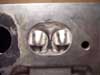
B202 intake
B212 intake (polished)
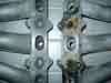
Comparison between B212 (left) and B202
(right)
.
Porting 1 on 1
Porting, opening up the "in and out" of the head to ensure more
and/or better flow.
B212 head cross-cut
There's a "rule of thumb" whilst porting and sizing up the valves and
ports.
1. Measure Bore
2. Use the following "formula" for Hemi Heads:
----------------
intake valve = 0.55*bore
intake port = 0.8*intake valve
exhaust valve = 0.8*intake valve
exhaust port = 0.8-1.0*exhaust valve
So lets size up the B202
Bore = 90
Which gives
Intake valve = 49.5 (stock valve = 32 -> 1.5 times smaller)
Exhaust valve = 39.6 (stock valve = 29 -> 1.3 times smaller)
This shows that according to the "rule of thumb" there's a lot of
possibilities to increase the flow. But mounting larger valves aren't easy and
requires special tools. so to the "regular" Joe, it's not the first
option. And I've seen cars that have been "dyno'd" with over 500 hp
with the stock valves.
But remember that higher valve lift will get increased flow through the valve
openings. So at "hotter" cam is a good step in the right direction.
But when we got a "hotter" cam and want even more flow... then
there's a way to increase the flow with a little work. Porting!
Remember this when porting:
Start with the intake. Check how much opening up of the ports are possible.
Make a template of the intake mount (this will also be the gasket template) and
put it on the cylinder head to see if it's possible to do that port-job. If it
looks feasible then mark the Cylinder head ports to measure out the outer limits
of the port-job. This is the port matching. Do the same on the Exhaust manifold.
Start with a "hard" grind stone to grind down the valve guide or
replace the guides with other canted ones (if replacement is at hand, mount
the new guides after the port-job is done). Then switch to a carbide burr
(oval or flame shaped) and start opening up the ports.
Remember to have lubricant (French chalk, kerosene, or WD-40, I recommend WD-40)
to help the flutes from clogging.
IMPORTANT, there are waterways and other hollows in the head so don't grind to deep.
When the base shape of the ports are done. Use Different sanding papers (like
Flap wheels, slot-shaft with paper and plain paper and finger) to work yourself
to the finished surface quality.
Never ever have a perfect shine on the intake side of a Cylinder head! Droplets
of fuel might form on the walls and drip into the cylinder. Atomised fuel and
air mixture can be compressed. Liquids cannot! (not easily, though). This can actually
harm the engine. So make sure that the intake port is glass blasted or similar.
This will help the air not to stick to the walls and the flow will be better.
This is just like a golf ball. A golf ball with grooves will fly longer than a
smooth one. Some professional "porters" actually makes some small
groves in the head behind the injectors mounts just to make sure that the needed
turbulence will be formed.
Case study, B202 Head
----------------------
Port, step 1.
Don't port! get a B212 head to start with.
B212 gasket mounted on a
B202 to show the difference
Case study, B212 Head
----------------------
Port, step 1.
Regrind of the valve guide and polishing of the ports.
Stock
intake
ported intake
What has been done on these pictures are:
- Grind of Valve guides
- Polish of ports
Case study, B212 Head
----------------------
Port, step 2.
Regrind of the valve guide and grind & polish of the ports
Stock
intake
Comparison between step
2(left) and step 1(right
What has been done on these pictures are:
- Grind of Valve guides
- Grind of ports (opened them up a bit and removed the valve guide ridge)
- Polish of ports .
Case study, B212 Head
----------------------
Port, step 3.
Regrind of the valve guide and major port-grind & polish of the ports.
<comparison picture of stock exhaust port & step 3 >
<comparison picture of stock intake port & step 3 >
<comparison picture of stock comb-space & step 3 >
<close-up picture of grooves >
What has been done on these pictures are:
- Grind of Valve guides
- Major grind of ports (opened them up much and removed the valve guide ridge)
- Polish of ports
- Grooves made to ensure turbulence.
Case study, B212 Head
----------------------
Port, step 4.
Regrind of the valve guide and major port-grind & polish of the ports.
Larger valves
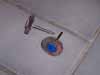
Tools of the trade:
The following tools is needed:
- Multipurpose grinder (Dremel or similar)
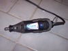
Dremel
- Grinders
<picture of oval burr>, <picture of flame burr>
Flapwheels
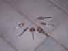
Grinders
Here's a
really good book on the subject!
GET IT WHILE YOU CAN!
It's out of print!
 How to Build, Modify & Power Tune Cylinder Heads